Blog 12: Comparing Floor Plans to Reference DXFs – Verifying Accuracy
A key feature of the floor plan extraction system is the ability to compare a generated floor plan with an existing architectural drawing in DXF format. This is especially valuable for verifying as-built conditions, detecting construction deviations, or auditing spaces during refurbishment projects.
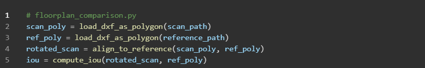
Through the GUI, users can load both a reference DXF file—typically supplied by the client or architect—and the floor plan extracted from LiDAR data. Once imported, the system normalises both files by aligning their orientation and centroids to establish a shared coordinate frame. This ensures the comparison process is geometrically meaningful.
The comparison algorithm evaluates the differences between the two shapes based on several key metrics:
Area mismatch: how much surface area differs
Wall lengths: total and individual differences between corresponding walls
IoU (Intersection over Union): a metric indicating spatial overlap
Angular deviations: differences in wall orientation
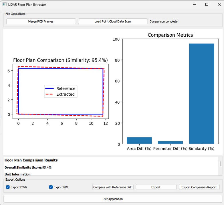
After computing these metrics, the GUI presents them in a comparison panel. The overlay visualisation highlights matching areas in one colour and mismatches in another, offering users an immediate understanding of alignment issues. A numerical similarity score between 0 and 1 is also generated to summarise accuracy at a glance.
A PDF report can be exported, including both the metric table and annotated graphics. This is particularly useful in construction settings where verification documents are required for sign-off or compliance.
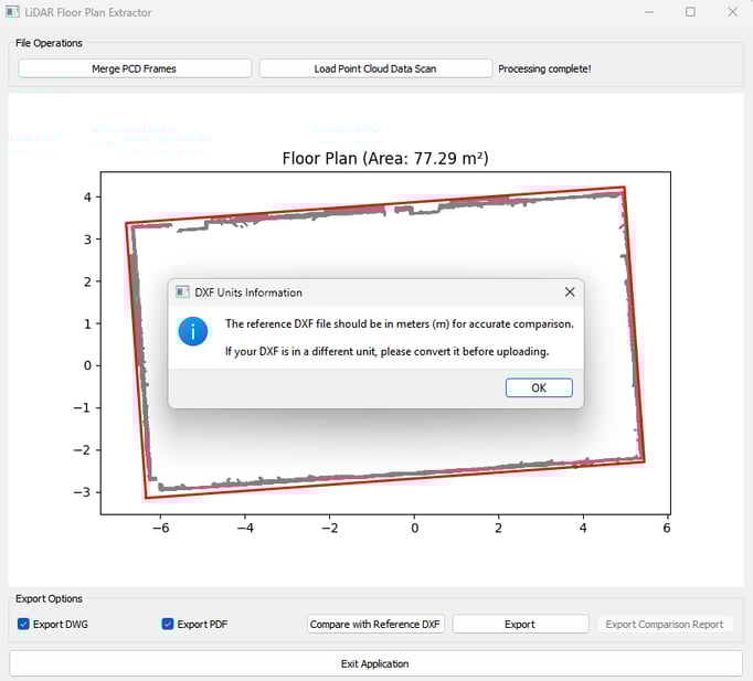
A warning before uploading DXF for comparison: ensure you use meters as the units of measurement in the file to avoid errors.